




GSCRV02 - Curved Stage Rail
- Specifications
- Technical Data
- Image Download
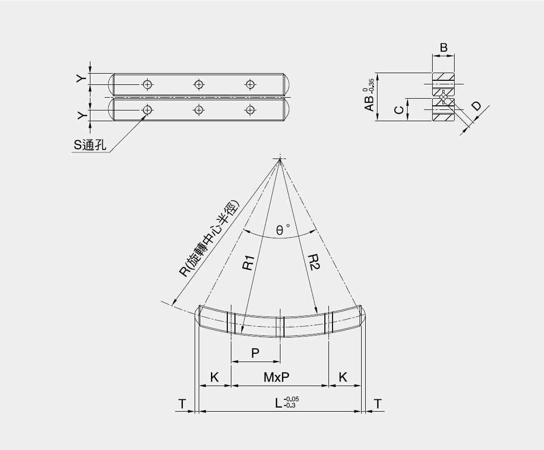
| Model | GSCRV0240-51-7G | GSCRV0240-70-7G | GSCRV0240-89.5-7G | GSCRV0260-65-11G | GSCRV0260-89-11G | GSCRV0260-113.5-11G | GSCRV0260-138.5-9G |
|---|---|---|---|---|---|---|---|
| Inquiry | Add To Inquiry | Add To Inquiry | Add To Inquiry | Add To Inquiry | Add To Inquiry | Add To Inquiry | Add To Inquiry |
| Rotation range | ± 8° | ± 6° | ± 5° | ± 8° | ± 8° | ± 6° | ± 5° |
| Roller diameter (D) (mm) | 2 | 2 | 2 | 2 | 2 | 2 | 2 |
| Number of rollers (G) | 7 | 7 | 7 | 11 | 11 | 11 | 9 |
| L (mm) | 40 | 40 | 40 | 60 | 60 | 60 | 60 |
| R (mm) | 51 | 70 | 89.5 | 65 | 89 | 113.5 | 138.5 |
| R1(mm) | 53.5 | 72.5 | 92 | 68 | 92 | 116.5 | 141.5 |
| R2(mm) | 48.5 | 67.5 | 87 | 62 | 86 | 110.5 | 135.5 |
| AB (mm) | 11.3 | 11.3 | 11.3 | 16 | 16 | 16 | 16 |
| B (mm) | 5 | 5 | 5 | 6 | 6 | 6 | 6 |
| C (mm) | 5.25 | 5.25 | 5.25 | 7.6 | 7.6 | 7.6 | 7.6 |
| Weight of 1 set (g) | 29 | 29 | 29 | 79 | 77 | 77 | 77 |
| Permissible load (F) (N) | 480 | 480 | 480 | 853 | 853 | 853 | 853 |
| Rated load - static (C0) (N) | 1420 | 1420 | 1420 | 2629 | 2629 | 2629 | 2629 |
| Rated load - Dynamic (C) (N) | 800 | 800 | 800 | 1320 | 1320 | 1320 | 1320 |
| θ° | 46.2° | 33.2° | 25.8° | 55° | 39.4° | 30.7° | 25° |
| T (mm) | 1.5 | 1.5 | 1.5 | 1.5 | 1.5 | 1.5 | 1.5 |
| S | M2 | M2 | M2 | M3 | M3 | M3 | M3 |
| Y (mm) | 2 | 2 | 2 | 2.5 | 2.5 | 2.5 | 2.5 |
| K (mm) | 8 | 8 | 8 | 11.25 | 11.25 | 11.25 | 11.25 |
| M*P (mm) | 2*12 | 2*12 | 2*12 | 3*12.5 | 3*12.5 | 3*12.5 | 3*12.5 |
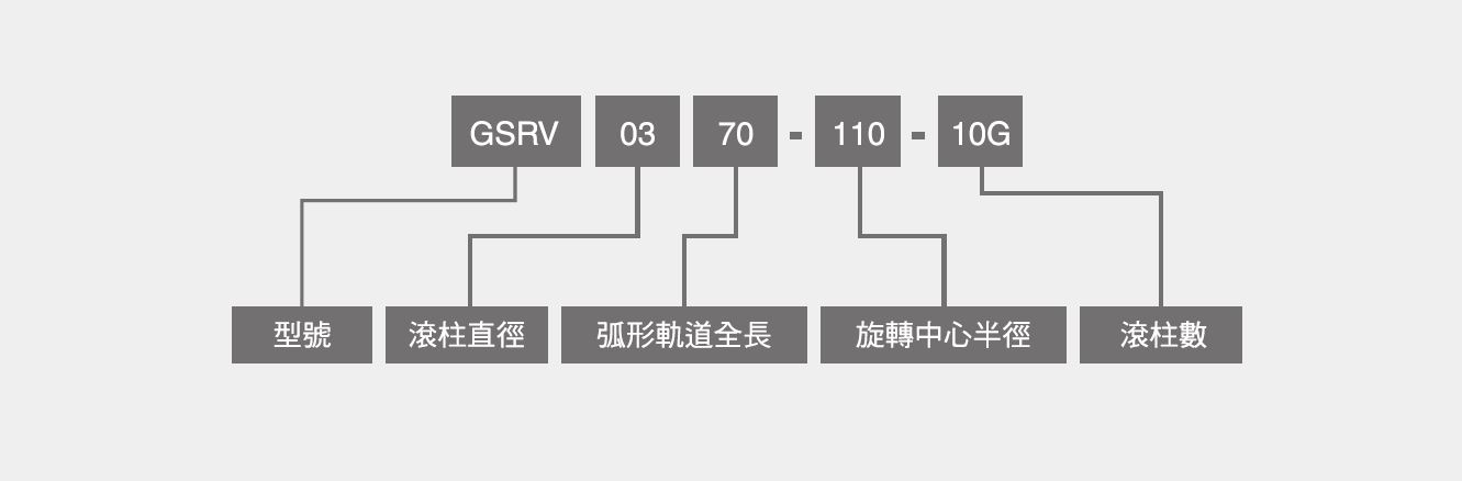
Model Description
Introduction to curved stage rails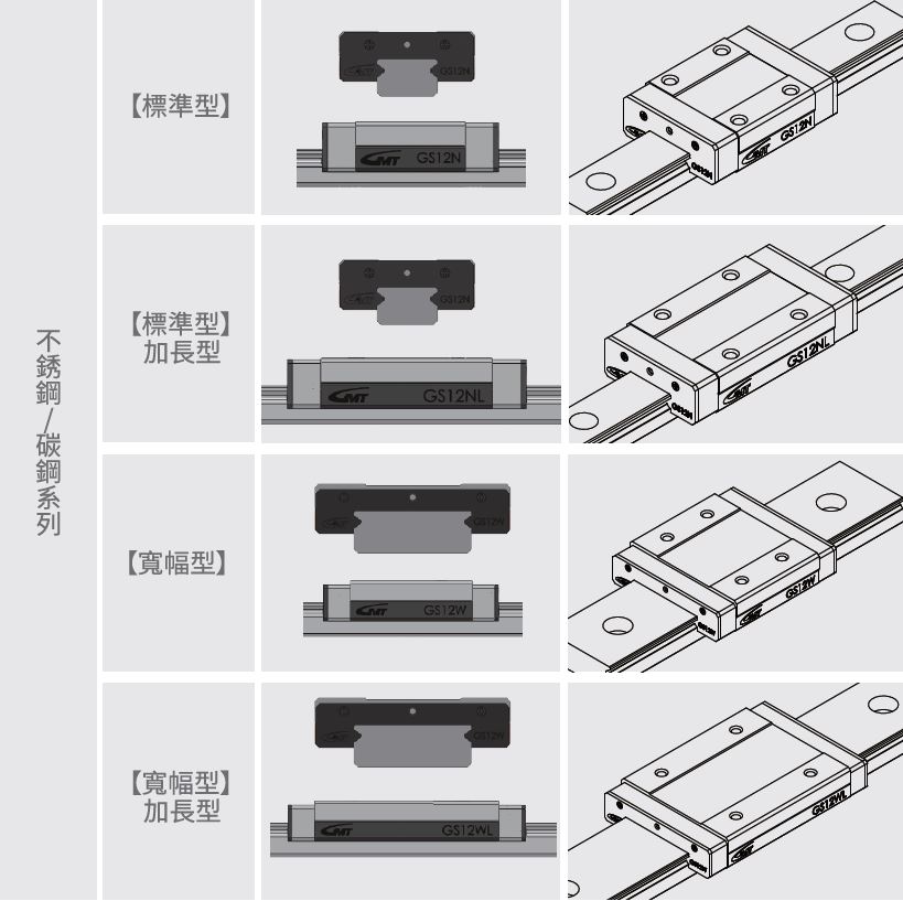
Structural Introduction
♦ arcstage rail
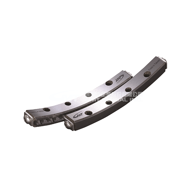
The arc track is a non-cyclic type of arc motion track, whose precision cross rollers have extremely low frictional resistance to provide stable arc movement.
It is mainly used for positioning operations where the rotation center position does not change and the tilt angle needs to be changed correctly. It can be applied to optical instruments and measuring devices that require high precision.
♦Product Structure
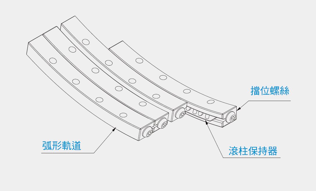
The curved track consists of a precision-ground V-shaped track and a curved roller retainer..
♦Track installation
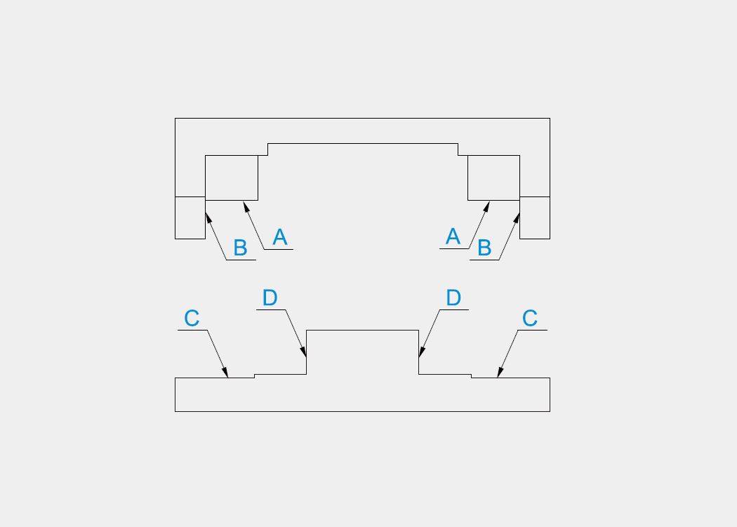
Mounting surface accuracy: As shown in the figure, the accuracy of surfaces A to D will directly affect the movement accuracy of the curved track.
♦Specifications and illustrations
One set has four curved tracks, two curved roller retainers, and eight tail screws..
♦Precautions
- Lubrication: Please use lithium soap-based lubricating grease.
- Retainer misalignment: When the curved track is used at high speed, under vibration or with unbalanced load, the retainer may deviate from the correct position. To minimize this, extra travel distance should be reserved to avoid excessive preload.
- Dust prevention: Depending on the operating environment, dust and foreign objects may seep into the interior of the curved track, preventing it from achieving its ideal performance. Therefore, if the curved track is installed in such harsh environments, it is recommended to use an external dust cover to protect the curved track.
- Baffle: The end face of the curved track is fitted with screws to prevent the curved retainer from falling off.
- Operating environment: For our company's curved tracks, the recommended operating environment temperature range is -20°C to 110°C.
- Principle of using complete sets: The accuracy of using curved tracks is based on the entire set, and the mutual error range is precisely controlled. Therefore, mixing different sets of curved tracks will lead to a decrease in accuracy. Please pay special attention during assembly.
- Adjustment: If the installation surface accuracy and preload are not fully adjusted, the motion accuracy will decrease, which may cause skewed movement or deformation, and may reduce the performance and lifespan. Please pay special attention when adjusting.
- Allowable load: This refers to the highest load value at which the total elastic deformation of the contact area is relatively small and smooth rolling can still be achieved when the contact stress on the rolling element and the track surface is at its maximum. In environments requiring high precision and smoothness, please ensure that the design and use are within the allowable load value.
Installation sequence
1. Please clean the mounting surfaces of the stage and base first, and avoid the introduction of foreign objects during assembly.
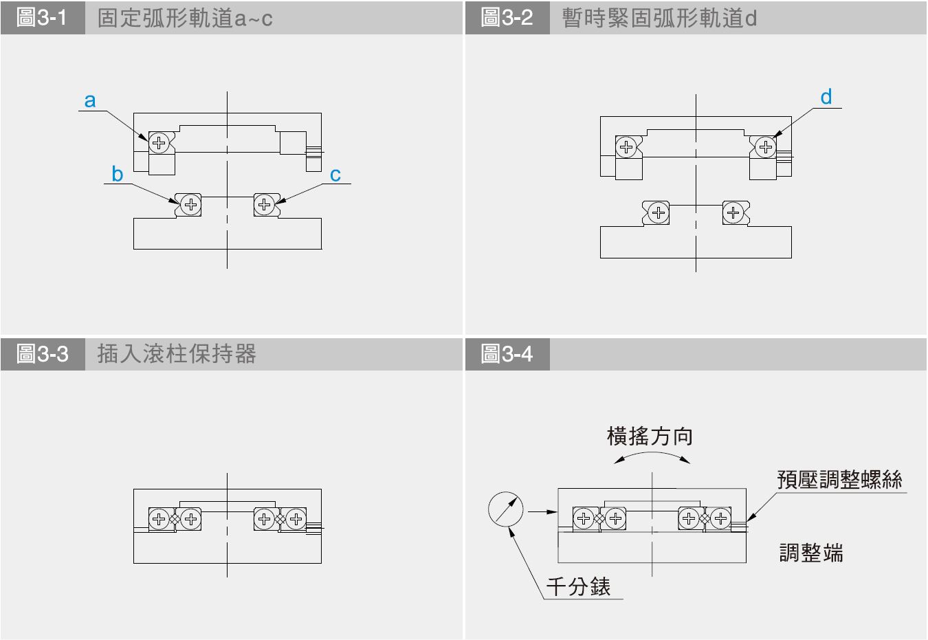
2. Apply low-viscosity lubricant to each mounting surface and tighten the a, b, and c arc rails and each mounting surface to the recommended torque. (Figure 3-1)
3. Temporarily lock the d-arc rail. (Figure 3-2)
4. Remove the stop screw from either end and insert the roller retainer to the middle position of the arc rail. After completing the above operations, reinstall the stop screw in its original position. (Figure 3-3)
5. Try moving the stage table left and right to the maximum stroke end, and adjust the roller retainer to the center position of the arc rail.
6. Install a dial indicator on the reference surface of the stage table. (Figure 3-4)
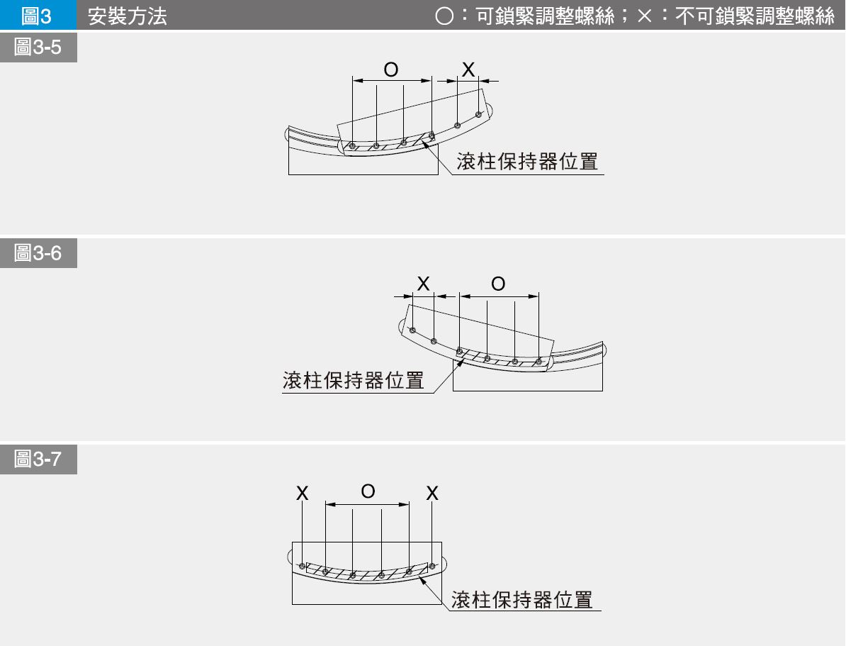
7. Move the stage to either end of its stroke and gently tighten the preload adjustment screw above the roller retainer. (Figure 3-5)
8. Move the stage to the other end of its travel and gently tighten the preload adjustment screw. (Figure 3-6)
9. Move the stage to the center position and gently tighten the center adjustment screw. (Figure 3-7)
10. Repeat steps (7) and (9) until there is no gap in the lateral direction. At this time, please be careful not to apply excessive preload.
11. Once there is no clearance in the lateral direction, when moving the stage table left and right, the pointer of the installed dial indicator will deflect to a minimum and remain stable. Please perform the final calibration of the preload according to the recommended tightening torque of the mounting screws for operations (7) and (9).
12. Finally, tighten the temporarily locked d-arc rail in the order of the preload adjustment screws.

Model