




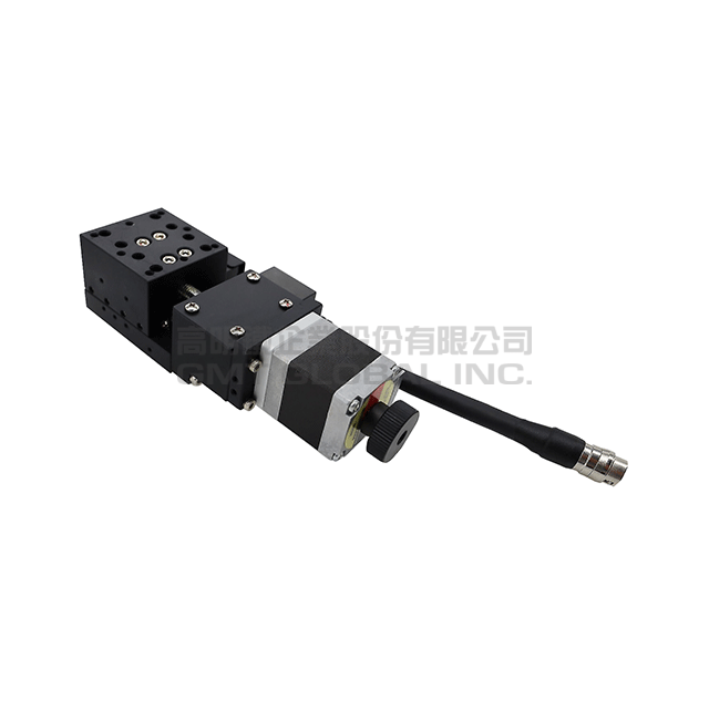
AX80130 - Ultra Precision
- Specifications
- Technical Data
- Image Download
| Model | AX80130-A2OPL | AX80130-A2OPR |
|---|---|---|
| Inquiry | Add To Inquiry | Add To Inquiry |
| Table Size (mm) | 80*130 | 80*130 |
| Travel Stroke (mm) | 70 | 70 |
| Drive Type | Ø8 ball screw, 1mm lead | Ø8 ball screw, 1mm lead |
| Rail | Cross roller guide | Cross roller guide |
| Stage Material | Aluminum Alloy | Aluminum Alloy |
| Surface Treatment | Black anodizing | Black anodizing |
| Main Unit Weight (Kgs) | 1.4 | 1.4 |
| Coupling | FAMMS16-5*5 | FAMMS16-5*5 |
| Accuracy Level | OP:Ultra Precision | OP:Ultra Precision |
| Wiring Method | L : Left wiring | R : Right wiring |
| Resolution(Pulse) (µm) | 1 (Full) / 0.5 (Half) | 1 (Full) / 0.5 (Half) |
| Max. Speed(Full Step) (mm/sec) | 10 | 10 |
| Positioning Precision (µm) | 8 | 8 |
| Repeatability Precision(µm) | ±0.3 | ±0.3 |
| Load Capacity (Kgf) | 20 | 20 |
| Missed Step (µm) | 1 | 1 |
| Pitch/Yaw | Pitch: < 25" / Yaw: < 20" | Pitch: < 25" / Yaw: < 20" |
| Parallelism (µm) | 30 | 30 |
| Dynamic Parallelism (µm) | 15 | 15 |
| Motor_Type/Shaft Numbers | 5-phase stepper high-resolution motor / ☐42 double shafts | 5-phase stepper high-resolution motor / ☐42 double shafts |
| Motor_Brand/Model | Orientalmotor / PKP544MN18B | Orientalmotor / PKP544MN18B |
| Driver Brand/Model | Orientalmotor / CVD Series - 5 Phase stepping motor (Additional options) | Orientalmotor / CVD Series - 5 Phase stepping motor (Additional options) |
| Connector type | 12-pin male connector HRS | 12-pin male connector HRS |
Multi-point repeated positioning accuracy
♦ Accuracy measurement description
1. Unidirectional positioning accuracy: within the range of the predetermined detection stroke, starting from a starting position, moving and positioning in a certain direction sequentially, and detecting the actual the difference between the movement value and the target movement value, and the maximum error value is taken. This value is the unidirectional positioning accuracy.
2. Multi-point repeated positioning accuracy: within the range of the predetermined detection stroke, when the mechanical program is executed, the position accuracy obtained by repeatedly running the same program code degree. Calculate the position deviation that occurs when the same position is repeated back and forth, and obtain the deviation value between the two.
♦ Precision introduction
1. Design the GMT high-level precision inspection method to meet the precision requirements of fiber coupling and semiconductor manufacturing process.
2. The detection of GMT high-end precision linear slide module series adopts multi-point repeated measurement, that is, multi-point quantity measurement within a fixed stroke range (points the amount is increased or decreased according to the length of the stroke), and the actual change of the round-trip position error is recorded, in pursuit of high precision and repeatability.
3. Through the non-contact laser interferometer measurement, to ensure that the unidirectional positioning is within 10μm, and the multipoint repetitive positioning accuracy is within 1.5μm. If there is a need for higher precision and precision, please contact the regional sales/business team.
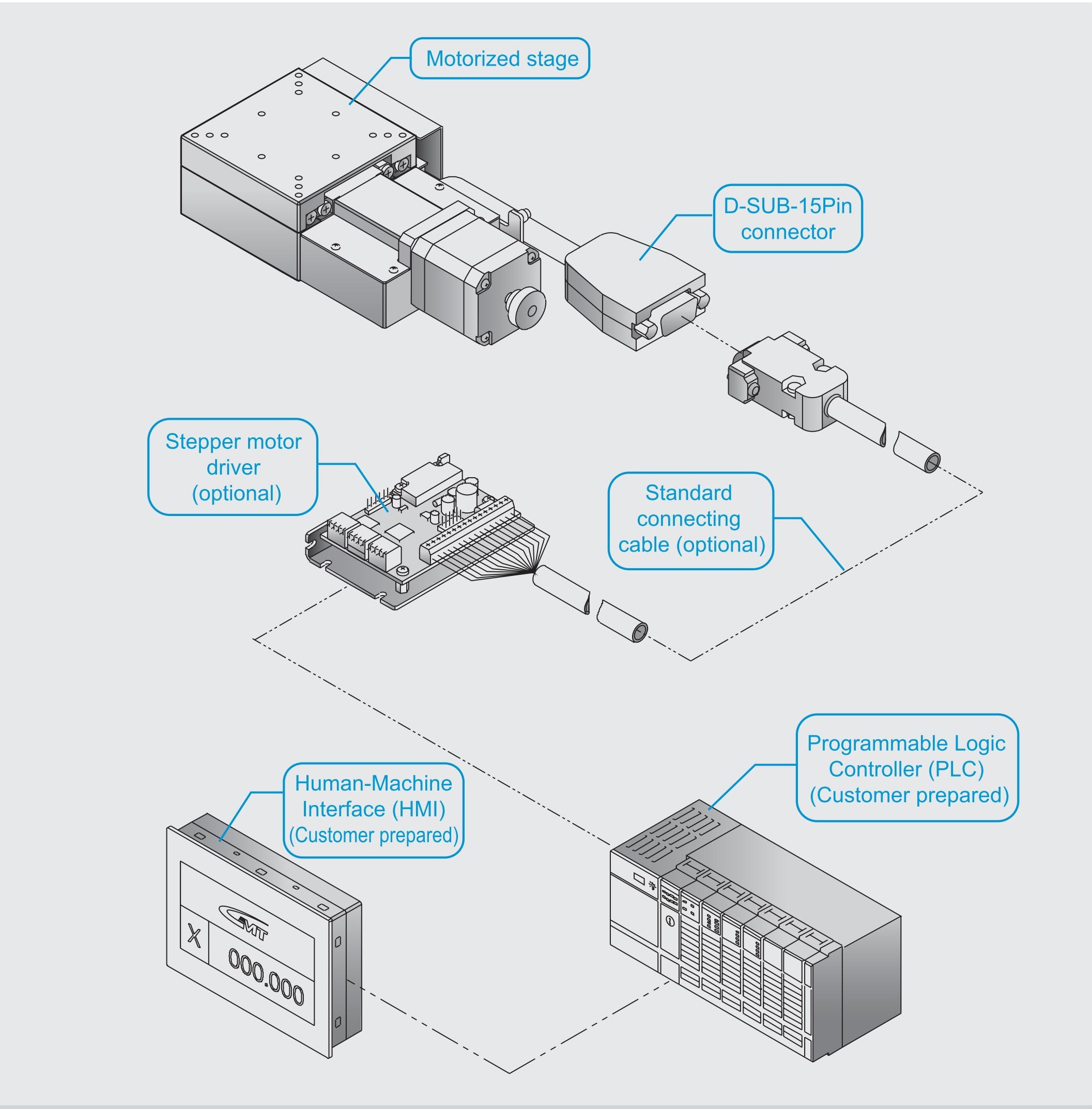
System Configuration Diagram
♦ For detailed specifications, please read the description for the stage and connecting cable.
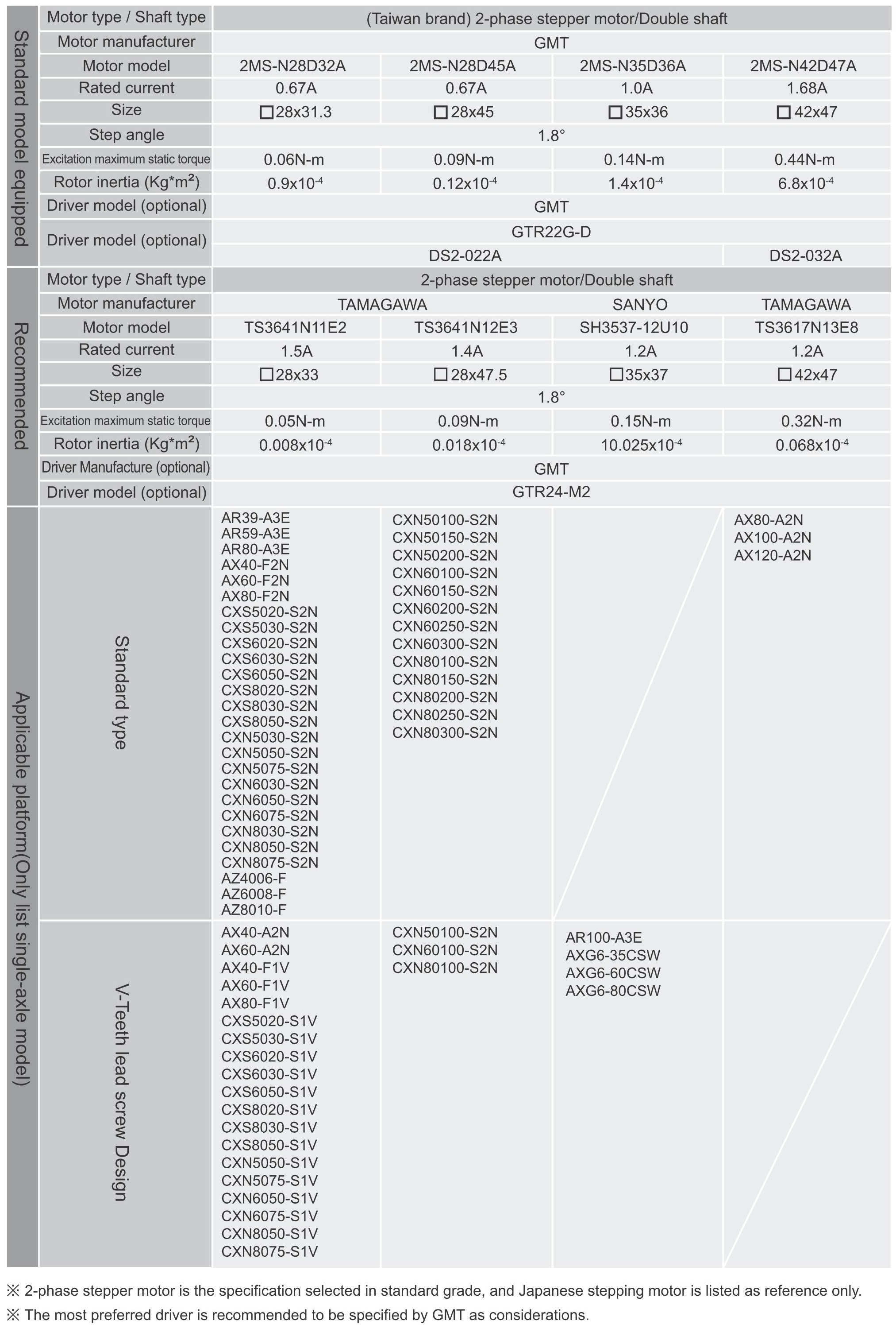
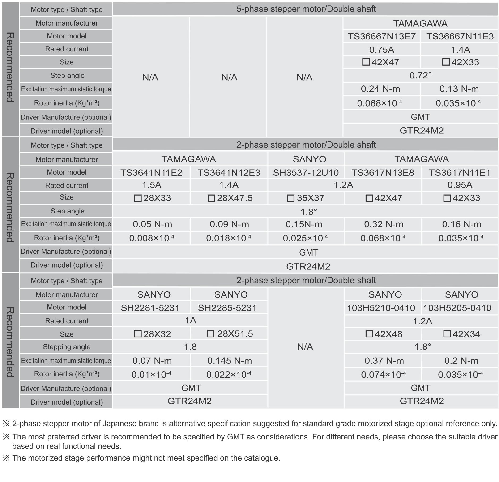
♦ For selection of driver, please refer to the cross-reference table for the motor/driver of the standard motorized stage or the GMT motor and driver catalog.
♦ The most preferred driver is recommended to be specified by GMT as considerations. For different needs, please choose the suitable driver based on real functional needs.
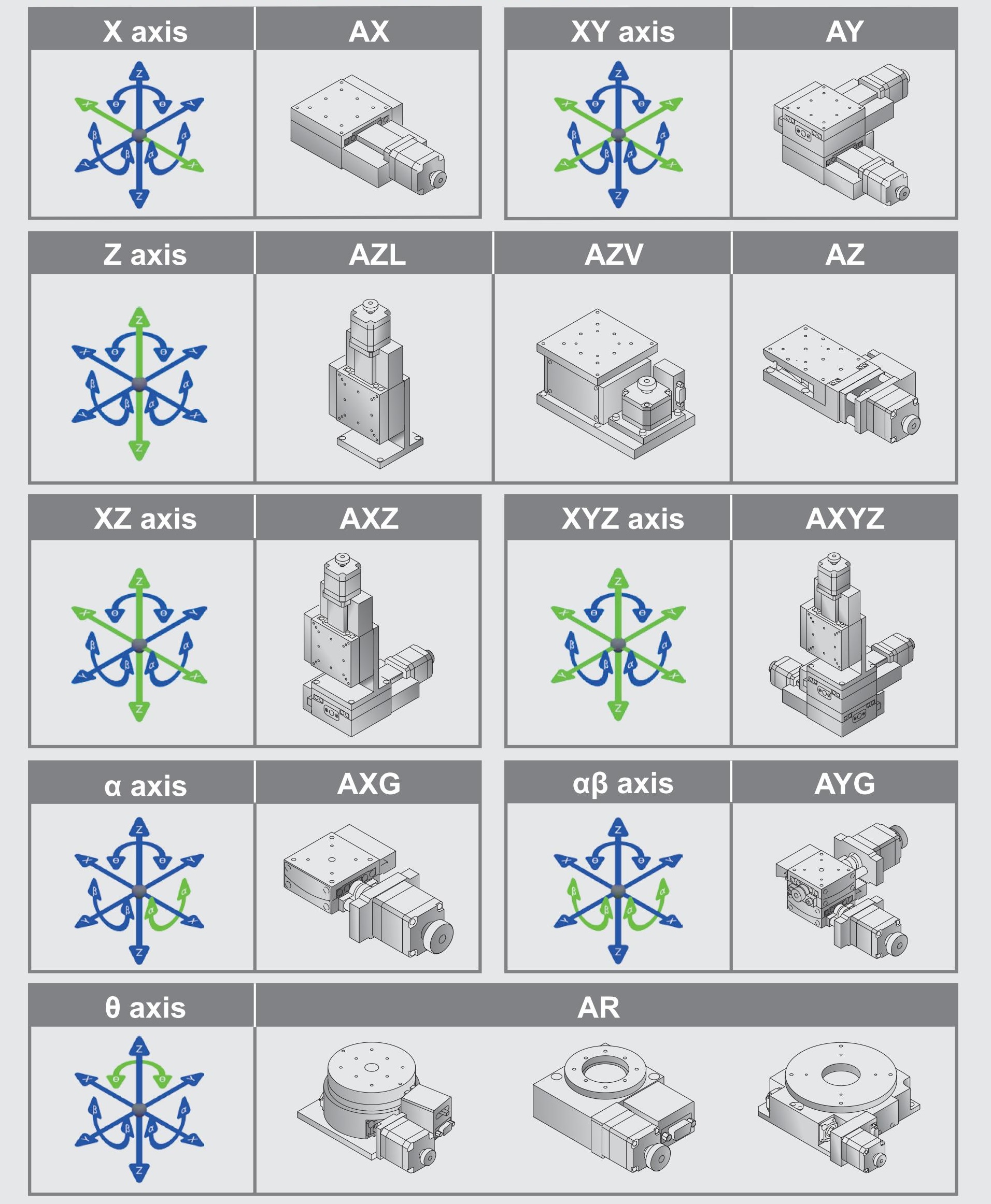
Axis Definition
GMT has defined different axis as the following figuration according to the movement direction:
Horizontal movement direction is X and Y axis.
Vertical movement direction is Z axis.
Movement around X, Y, Z axis is defined to α axis, β axis, and θ axis.
Green arrows present the specified axis movement direction.
Motor/driver

Model