




Precision Motorized Stages
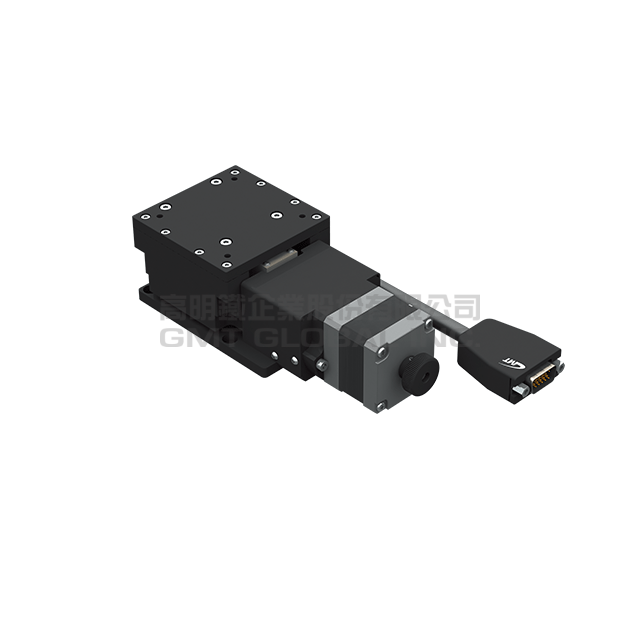
AZ-HP - Hi-Resolution Precision
★
Guide-Crossed-roller Guide, In structure, V-groove and crossed roller acquire movement in high accuracy and capacity by linear transmission to act a high precision movement and load capacity performance.
★
Transmission Parts-Ball screw, It transmits through the ball involving in the locknut and screw to reach the accuracy and longer operation lifetime.
★
Material: Aluminum Alloy, Stainless Steel
★
Model Shown: AZ70-A6HPR-HD
- Specifications
- Technical Data
- Image Download
Total of 4 models
| Model | AZ7010-A6HPR-MD | AZ7010-S6HPR-MD | AZ7020-A6HPR-MD | AZ7020-S6HPR-MD |
|---|---|---|---|---|
| Inquiry | Add To Inquiry | Add To Inquiry | Add To Inquiry | Add To Inquiry |
| Table Size (mm) | 70*70 | 70*70 | 70*70 | 70*70 |
| Travel Stroke (mm) | 10 | 10 | 20 | 20 |
| Drive Type | Ø8 ball screw, 1mm lead | Ø8 ball screw, 1mm lead | Ø8 ball screw, 1mm lead | Ø8 ball screw, 1mm lead |
| Rail | Cross roller guide | Cross roller guide | Cross roller guide | Cross roller guide |
| Stage Material | Aluminum Alloy | Stainless steel | Aluminum Alloy | Stainless steel |
| Surface Treatment | Black anodized | Chemical nickel plating | Black anodized | Chemical nickel plating |
| Main Unit Weight (Kg) | 1.1 | 1.7 | 1.4 | 2.1 |
| Coupling | FSMMS12-4*5 | FSMMS12-4*5 | FSMMS12-4*5 | FSMMS12-4*5 |
| Accuracy Level | HP: High-resolution power type | HP: High-resolution power type | HP: High-resolution power type | HP: High-resolution power type |
| Wiring Method | R : Right wiring | R : Right wiring | R : Right wiring | R : Right wiring |
| Wiring Method | L : Left wiring | L : Left wiring | L : Left wiring | L : Left wiring |
| Resolution(Pulse) (µm) | 0.5 (Full) / 0.25 (Half) | 0.5 (Full) / 0.25 (Half) | 0.5 (Full) / 0.25 (Half) | 0.5 (Full) / 0.25 (Half) |
| Max. Speed(Full Step) (mm/sec) | 5 | 5 | 5 | 5 |
| Positioning Precision (µm) | 15 | 15 | 20 | 20 |
| Repeatability Precision(µm) | ± 0.5 | ± 0.5 | ± 0.5 | ± 0.5 |
| Load Capacity (Kgf) | 8 | 10 | 8 | 10 |
| Missed Step (µm) | 1 | 1 | 1 | 1 |
| Parallelism (µm) | 30 | 30 | 30 | 30 |
| Dynamic Straightness (µm) | 8 | 8 | 10 | 10 |
| Motor Type / Output Shaft Type | 5-phase stepper motor / ☐ 42 dual output shafts | 5-phase stepper motor / ☐ 42 dual output shafts | 5-phase stepper motor / ☐ 42 dual output shafts | 5-phase stepper motor / ☐ 42 dual output shafts |
| Motor Brand/Model | Orientalmotor / PKP544MN18B | Orientalmotor / PKP544MN18B | Orientalmotor / PKP544MN18B | Orientalmotor / PKP544MN18B |
| Driver Brand/Model | Please refer to the motor/drive comparison table. | Please refer to the motor/drive comparison table. | Please refer to the motor/drive comparison table. | Please refer to the motor/drive comparison table. |
| Connector_Stage side connector | 15-Pin male end connetor D-SUB / 12-Pin male end connetor HRS | 15-Pin male end connetor D-SUB / 12-Pin male end connetor HRS | 15-Pin male end connetor D-SUB / 12-Pin male end connetor HRS | 15-Pin male end connetor D-SUB / 12-Pin male end connetor HRS |
| Connector - Controller Side Connector | 15-pin female connector D-SUB / 12-pin female connector HRS (optional) | 15-pin female connector D-SUB / 12-pin female connector HRS (optional) | 15-pin female connector D-SUB / 12-pin female connector HRS (optional) | 15-pin female connector D-SUB / 12-pin female connector HRS (optional) |
| Sensor_Travel Origin Sensor | GMT sensor | GMT sensor | GMT sensor | GMT sensor |
| Sensor_Stroke Limit Sensor | GMT sensor | GMT sensor | GMT sensor | GMT sensor |
| Sensor - Motor Proximity Origin Sensor | N/A | N/A | N/A | N/A |
| Sensor_Power Voltage | 24V ± 10% | 24V ± 10% | 24V ± 10% | 24V ± 10% |
| Sensor Control Output | NPN open collector output under 24V 8mA | NPN open collector output under 24V 8mA | NPN open collector output under 24V 8mA | NPN open collector output under 24V 8mA |
| Sensor Output Control | Detection (during sensing): Output transistor OFF (non-conducting) | Detection (during sensing): Output transistor OFF (non-conducting) | Detection (during sensing): Output transistor OFF (non-conducting) | Detection (during sensing): Output transistor OFF (non-conducting) |
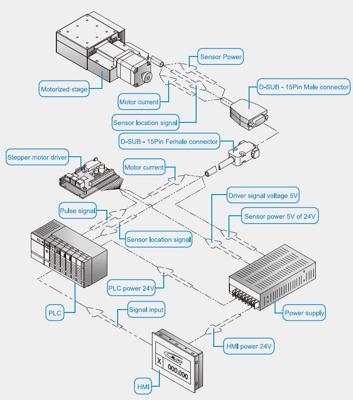
Product Overview
System Configuration Diagram
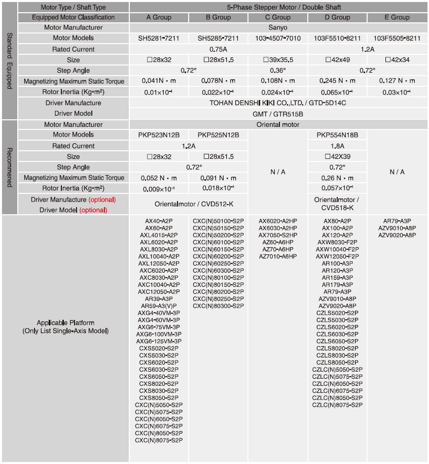
♦ For selection of the drivers preferred, please refer to the reference table or the catalogue of Motor・Driver.
♦ All of the drivers chosed are the specification of GMT preferred. For different needs, please choose the suitable drivers according to real functional needs.
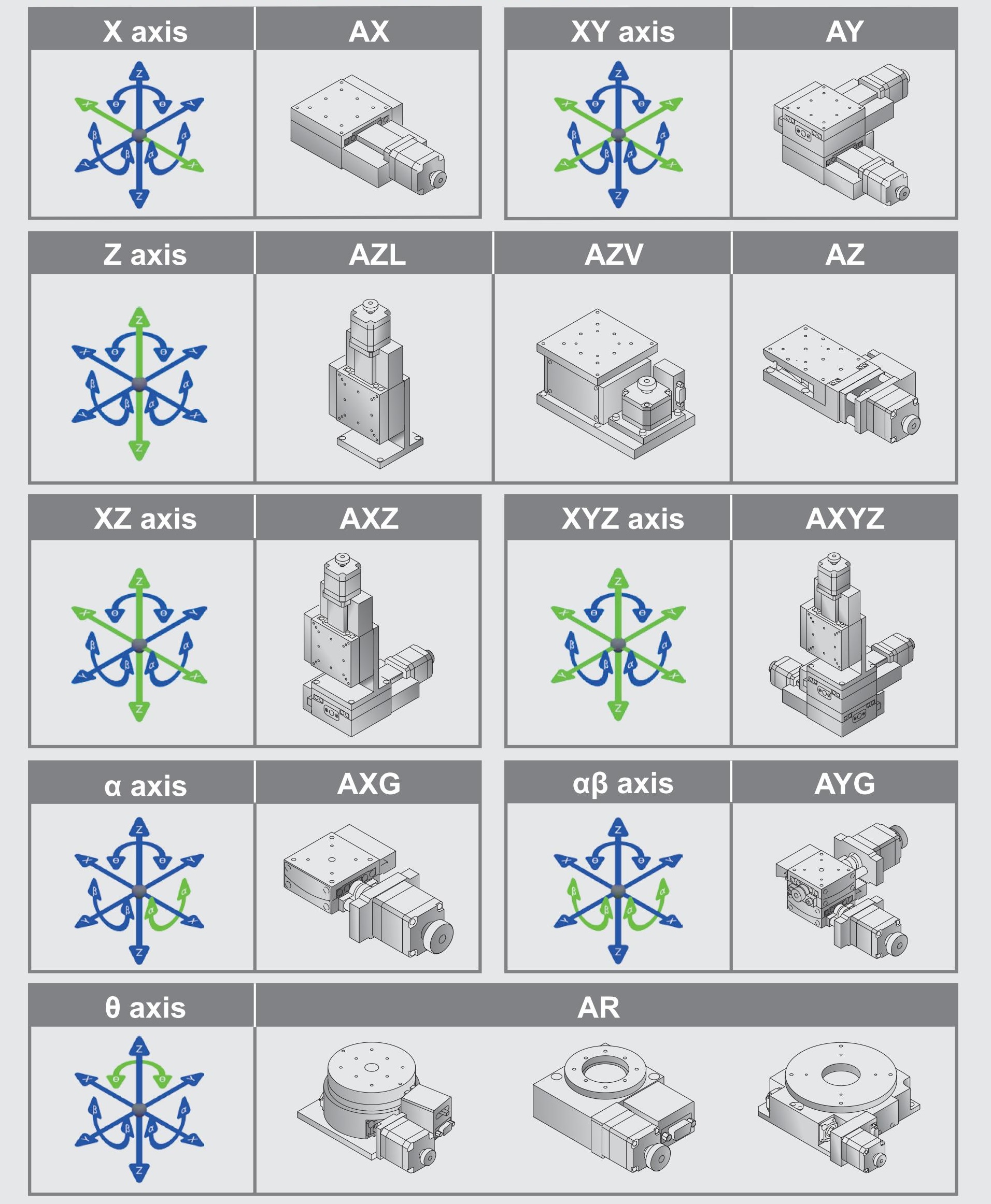
Axis Definition
GMT has defined different axis as the following figuration according to the movement direction:
Horizontal movement direction is X and Y axis.
Vertical movement direction is Z axis.
Movement around X, Y, Z axis is defined to α axis, β axis, and θ axis.
Green arrows present the specified axis movement direction.
Motor•driver Reference Table
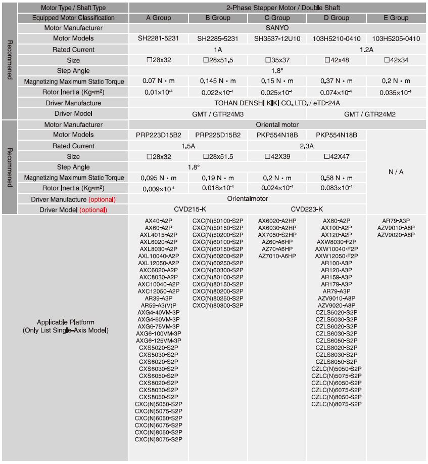
Model
AZ7010-A6HPR



AZ7010-S6HPR
AZ7020-A6HPR
AZ7020-S6HPR