




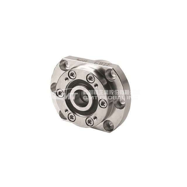
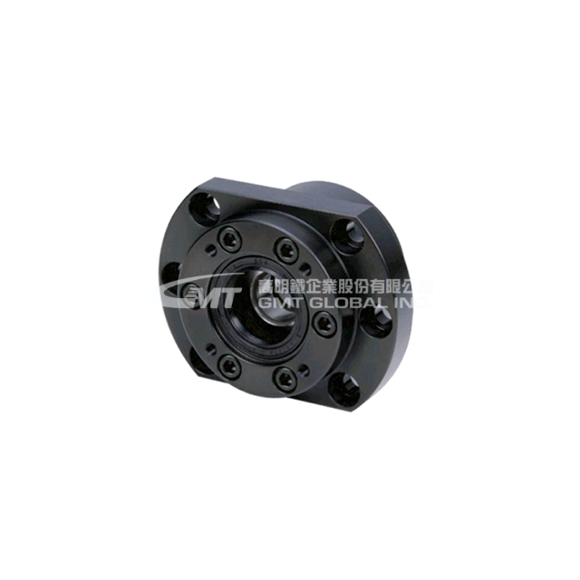
GWFF30
- Specifications
- Technical Data
- Image Download
| Model | GWFF30-DF | GWFF30-DFD |
|---|---|---|
| Inquiry | Add To Inquiry | Add To Inquiry |
| Material | S50C | S50C |
| Surface Treatment | B: Dyed black | B: Dyed black |
| Surface Treatment | N: Electroless nickel | N: Electroless nickel |
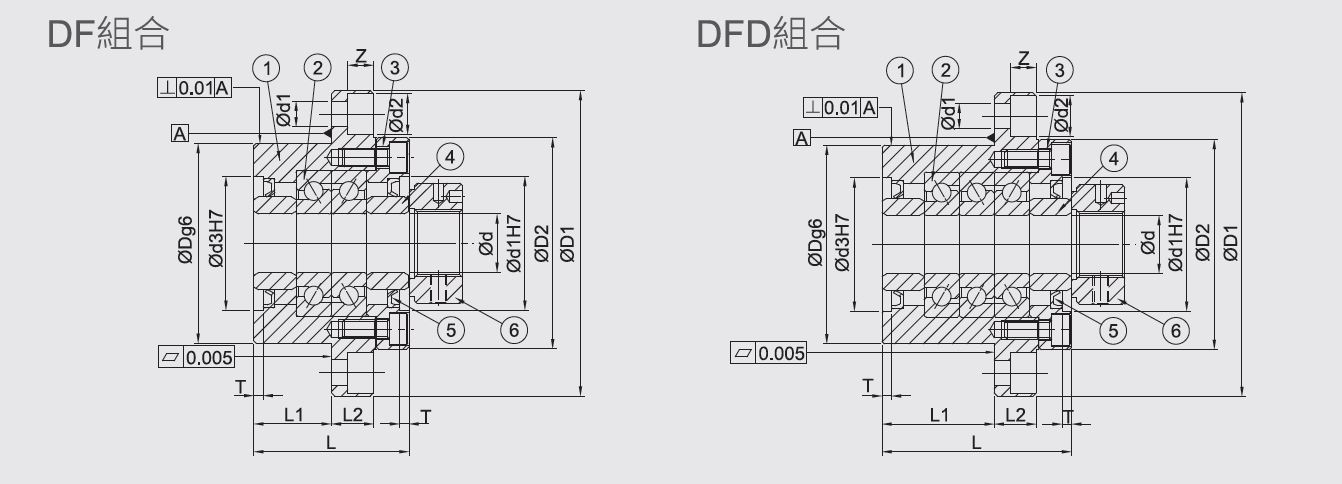
| bearing assembly | DF: Face-to-face combination | DFD: Three-column combination |
| Ød (mm) | 30 | 30 |
| ØD (mm) | 85 | 85 |
| ØD1 (mm) | 130 | 130 |
| ØD2 (mm) | 90 | 90 |
| Ød3 (mm) | 57 | 57 |
| L (mm) | 66 | 81 |
| L1 (mm) | 33 | 48 |
| L2 (mm) | 18 | 18 |
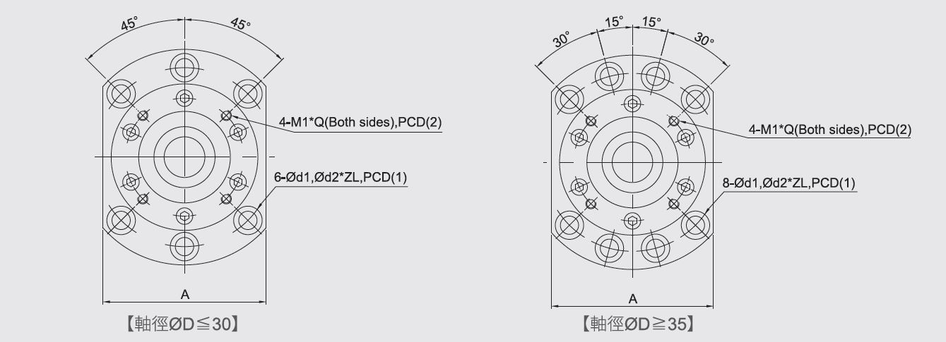
| A (mm) | 100 | 100 |
| PCD (1) (mm) | 110 | 110 |
| PCD (2) (mm) | 70 | 70 |
| Ød1 (mm) | 10.7 | 10.7 |
| Ød2 (mm) | 17.5 | 17.5 |
| Z (mm) | 11 | 11 |
| T (mm) | 4 | 4 |
| M1 (mm) | M6 | M6 |
| Q (mm) | 14 | 14 |
| Single roller load - Basic dynamic load (C) (N) | 29200 | 47500 |
| Axial limit load (N) | 43000 | 86000 |
| Preload (N) | 3350 | 4500 |
| Axial stiffness (N/um) | 1030 | 1520 |
| Starting torque (N・cm) | twenty four | 33 |
| Ød (mm) | 30 | 30 |
| L3 (mm) | 89 | 104 |
| L4 (mm) | 26 | 26 |
| M (mm) | M30 x P1.5 | M30 x P1.5 |
| Ød4 (mm) | 50 | 50 |
| L5 (mm) | 20 | 20 |
| Weight (Kg) | 3 | 3.3 |
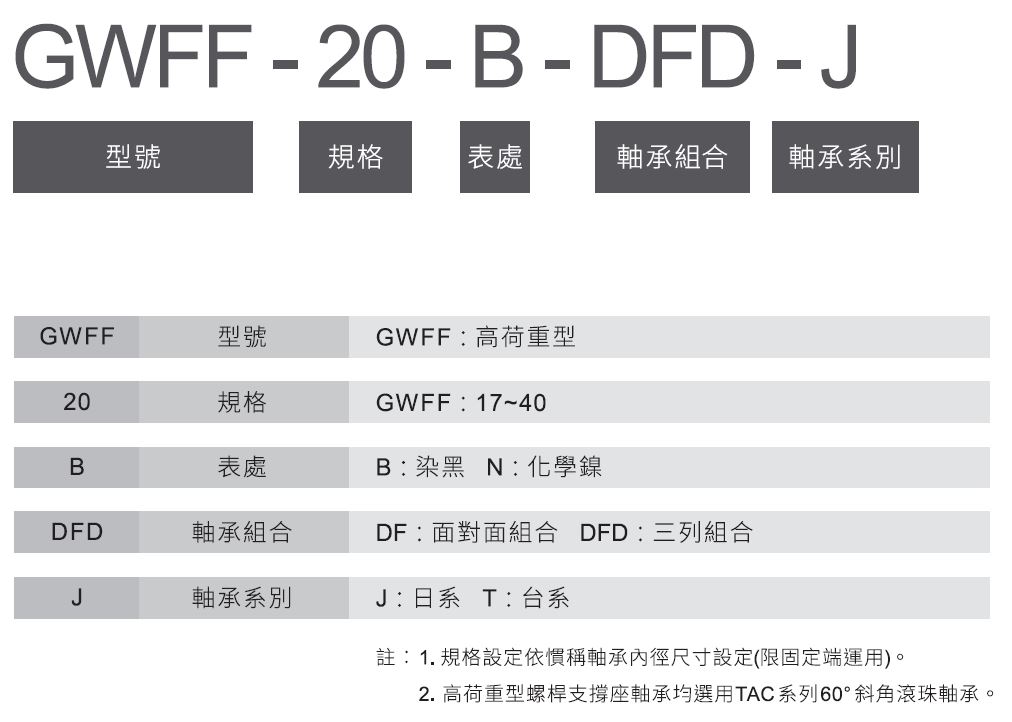
Model Description
Recommended shaft end machining dimensions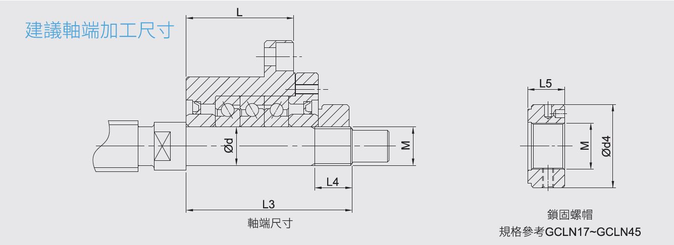
Introduction to screw support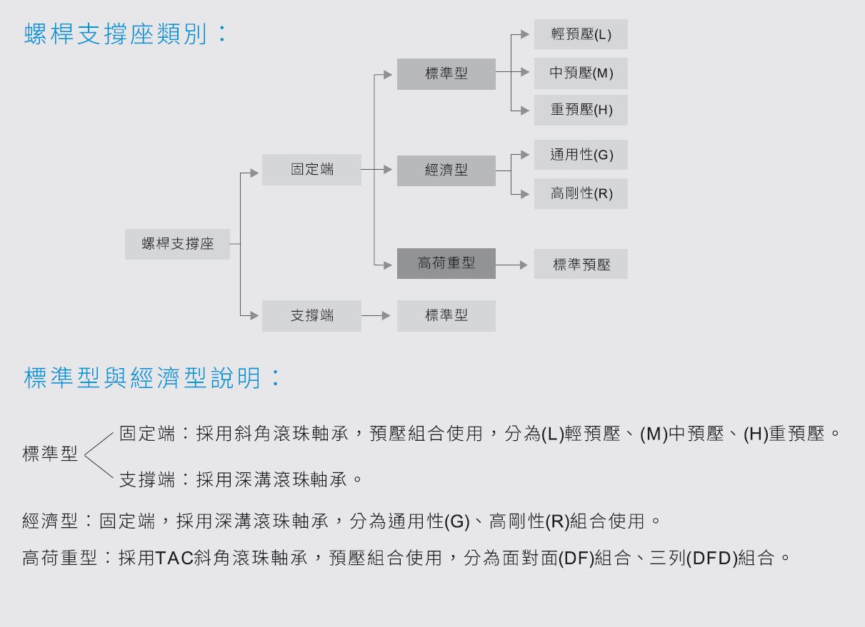
♦ Pre-compression and application instructions
- Light preload (L)
* Applicable conditions: Equipment with a fixed load direction that requires low vibration, low impact force, low sliding resistance, or high speed.
* Suggested applications: beam welding machinery, automatic packaging machines, light CNC milling machines, general industrial machinery moving shafts, automatic door and window processing machines, welding machines, fusing machines, tool changing devices, binding machinery, various material supply devices, CNC engraving and milling machines.
- Medium preloading (M)
* Applicable conditions: Devices with cantilever loads or torques, single-axis applications, and light-load, high-precision equipment.
* Suggested applications: Grinding machine table feed axes, automatic coating machines, measuring instruments, various high-speed material supply devices, precision XY platforms, axes of general industrial machinery, drilling machines for printed circuit boards, electrical discharge machining (EDM) machines, industrial robots, NC lathes.
- Heavy preloading (H)
* Applicable conditions: Equipment requiring high rigidity, and subjected to large vibrations, impacts, and high torques.
* Suggested applications: machining center spindles, NC lathes, Z-axis of machine tools, milling machines, grinding wheel feed axes of grinding machines.
♦GMT screw support preload purpose explanation
- Objective: 1. To improve the rotational accuracy of the shaft.
2. Improve shaft rigidity
3. Prevent shaft vibration and abnormal noise.
4. Prevent vibration and impact marks during bearing shutdown.
- What is preload: Using the rated load (N) value and the measured (L) value of a pair of bearings, after being placed into the fixed end, pressure is applied to the outer ring by the bearing cap to connect the two shafts and generate preload.
♦Product Selection Considerations
-[model]Select the screw support series according to the screw support 'installation method'.
Installation method:
1. Flat mounting type: GAK, GBK, GEK, GAF, GBF, GEF, GSW, GSWE, GUN, GTN.
2. Embedded installation type: GFK, GFF, GRW, GRWE, GUR, GTR.
-[Specification]Then select the model based on the screw's outer diameter and center height.
-[grade]Distinguished by standard and economy models.
-[Pre-compression]Bearing preload can be selected according to customer requirements.
-[Table format]The surface treatment method depends on the usage environment: electroless nickel plating or blackening.
Blackening: Under normal conditions (low humidity).
Electroless nickel (also known as electroless nickel): Cleanroom.
-[Bearing Series]There are Japanese and Taiwanese bearings.
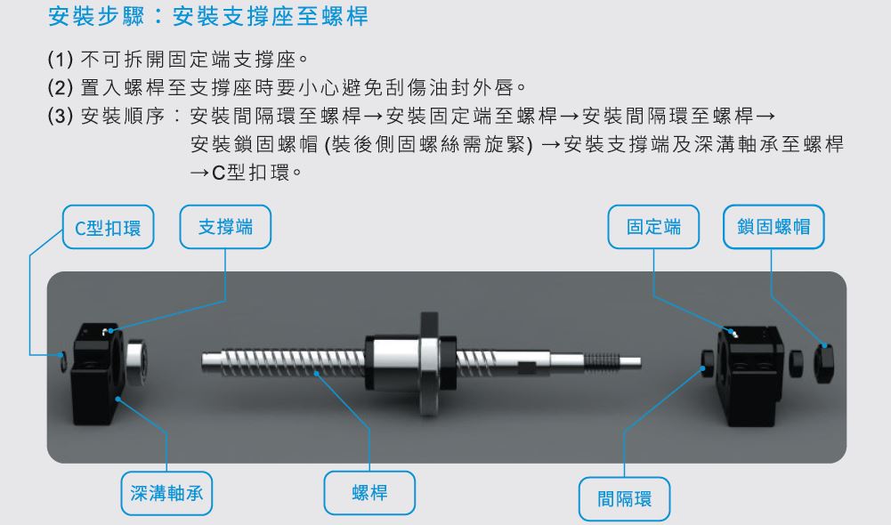
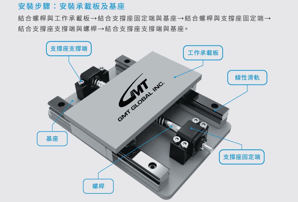
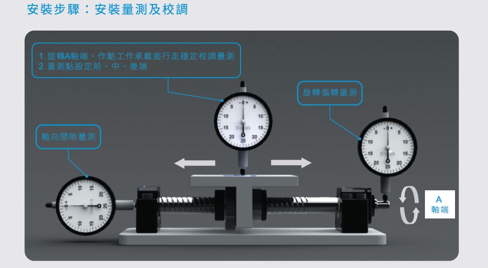
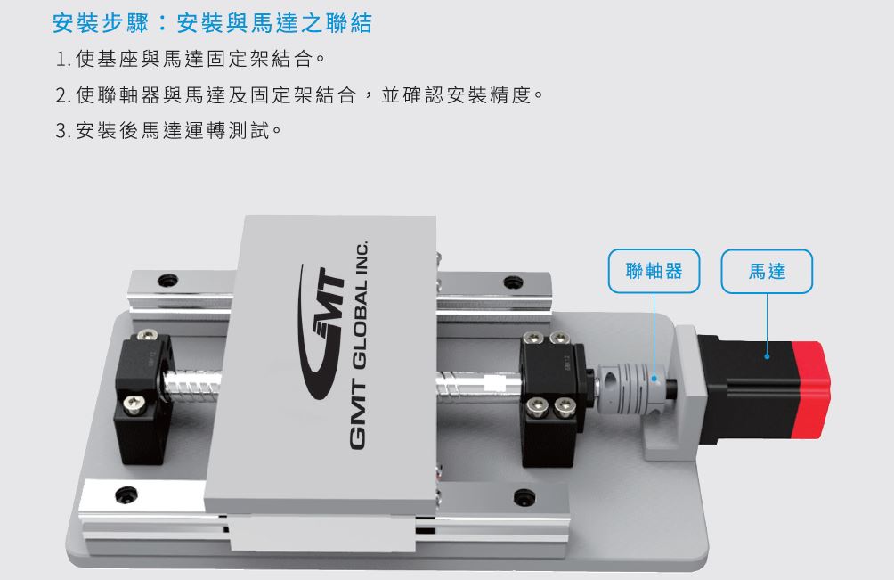
Screw support assembly example & steps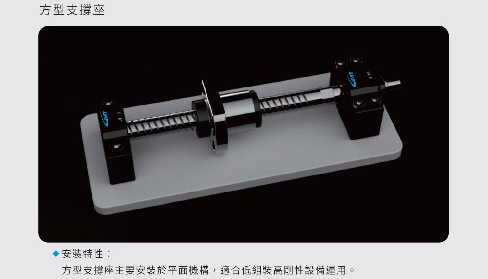
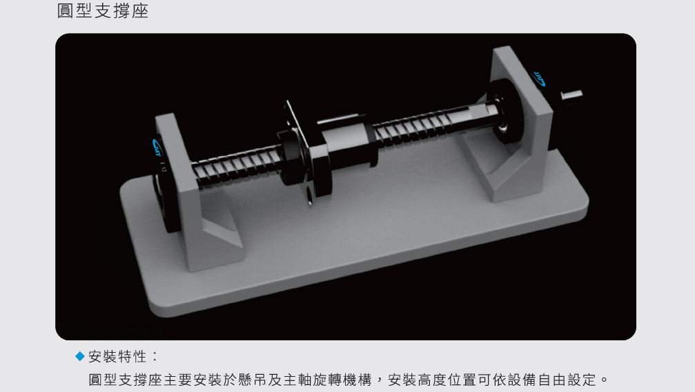
Model