




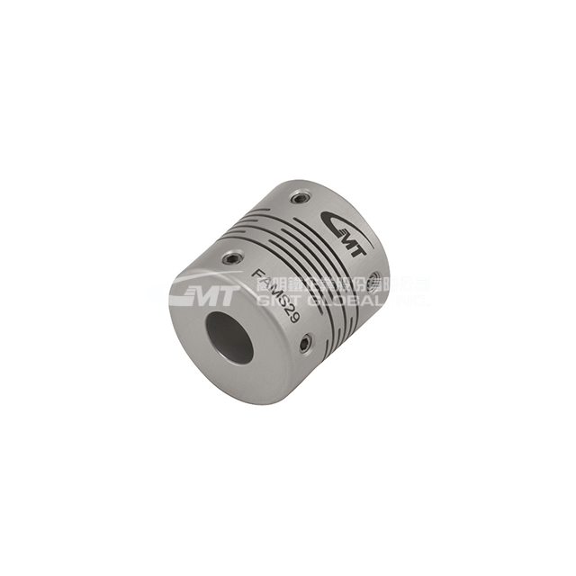
FAMS34
- Specifications
- Technical Data
- Image Download
| Model | FAMS34-10(Ød1) | FAMS34-11(Ød1) | FAMS34-12(Ød1) | FAMS34-14(Ød1) | FAMS34-15(Ød1) | FAMS34-16(Ød1) |
|---|---|---|---|---|---|---|
| Inquiry | Add To Inquiry | Add To Inquiry | Add To Inquiry | Add To Inquiry | Add To Inquiry | Add To Inquiry |
| Material | Super Duralumin | Super Duralumin | Super Duralumin | Super Duralumin | Super Duralumin | Super Duralumin |
| Surface Treatment | Anodizing | Anodizing | Anodizing | Anodizing | Anodizing | Anodizing |
| Accessories | Stop-fit screws | Stop-fit screws | Stop-fit screws | Stop-fit screws | Stop-fit screws | Stop-fit screws |
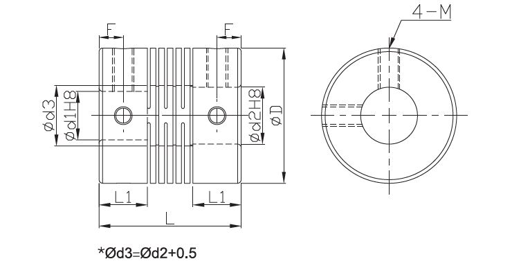
| Ød2 | 14 | 14 | 12 / 14 / 16 | 14 / 15 / 16 | 15 / 16 | 16 |
| L (mm) | 35 | 35 | 35 | 35 | 35 | 35 |
| L1 (mm) | 12 | 12 | 12 | 12 | 12 | 12 |
| F (mm) | 6 | 6 | 6 | 6 | 6 | 6 |
| M (mm) | 5 | 5 | 5 | 5 | 5 | 5 |
| Permissible torque (N・m) | 3 | 3 | 3 | 3 | 3 | 3 |
| Installation tolerance_Offset angle (°) | 0.5 | 0.5 | 0.5 | 0.5 | 0.5 | 0.5 |
| Installation tolerance deviation - Eccentricity (mm) | 0.05 | 0.05 | 0.05 | 0.05 | 0.05 | 0.05 |
| Installation tolerance_Axial displacement (mm) | ± 0.1 | ± 0.1 | ± 0.1 | ± 0.1 | ± 0.1 | ± 0.1 |
| Static elastic modulus (N·m / rad) | 2200 | 2200 | 2200 | 2200 | 2200 | 2200 |
| Maximum rotational speed (r/min)-1) | 11000 | 11000 | 11000 | 11000 | 11000 | 11000 |
| Moment of inertia (kg·m)2) | (Calculated based on the maximum aperture) | (Calculated based on the maximum aperture) | (Calculated based on the maximum aperture) | (Calculated based on the maximum aperture) | (Calculated based on the maximum aperture) | (Calculated based on the maximum aperture) |
| Moment of inertia (kg·m)2) | 1.1*10-5 | 1.1*10-5 | 1.1*10-5 | 1.1*10-5 | 1.1*10-5 | 1.1*10-5 |
| Screw tightening torque (N・m) | 4 | 4 | 4 | 4 | 4 | 4 |
| Mass (g) | (Calculated based on the maximum aperture) | (Calculated based on the maximum aperture) | (Calculated based on the maximum aperture) | (Calculated based on the maximum aperture) | (Calculated based on the maximum aperture) | (Calculated based on the maximum aperture) |
| Mass (g) | 64 | 64 | 64 | 64 | 64 | 64 |
Model Description
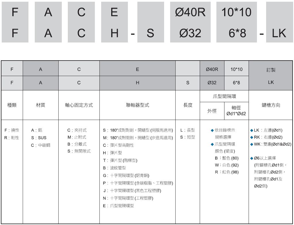
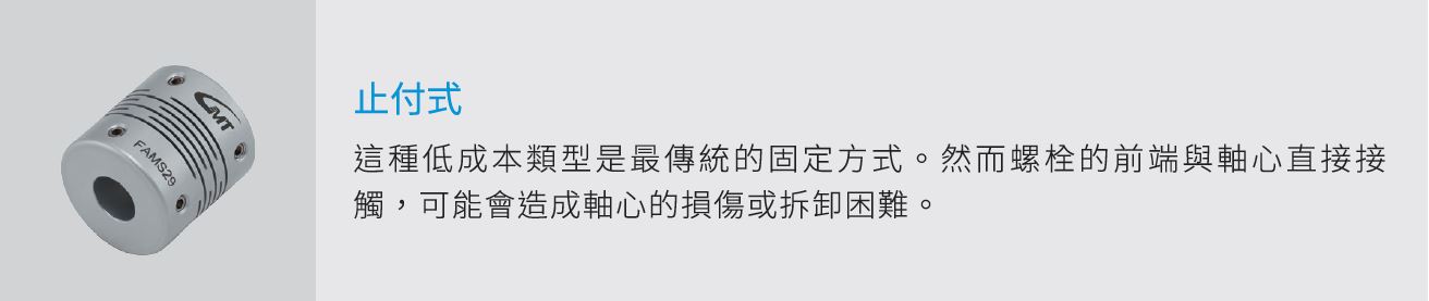
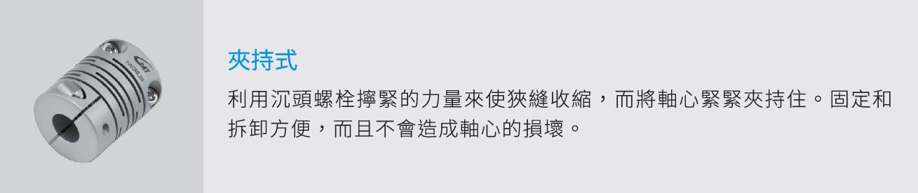
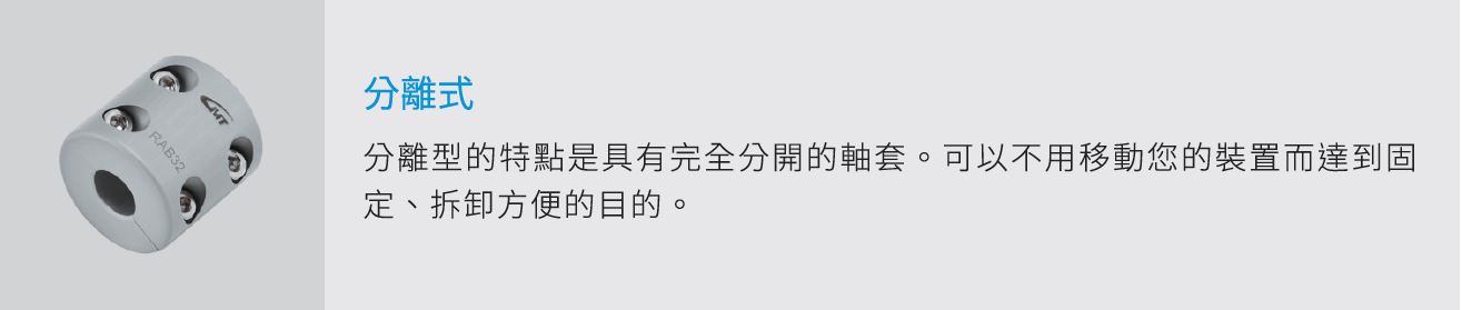
Coupling fixing method
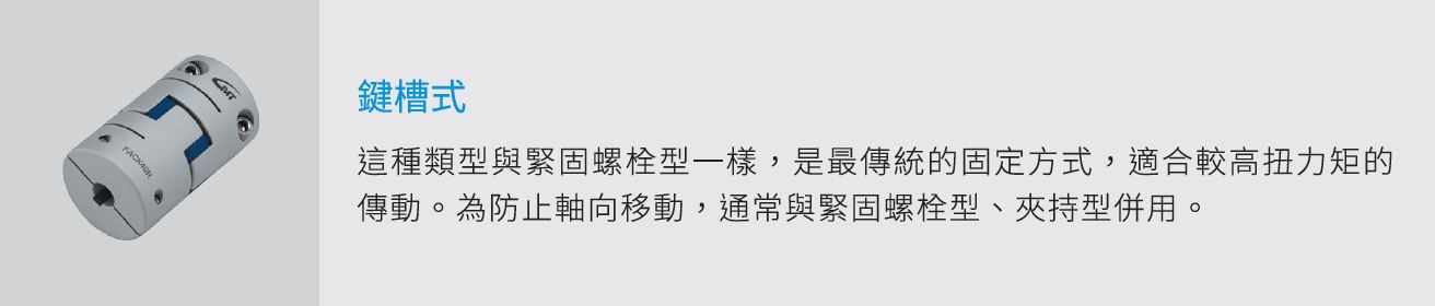
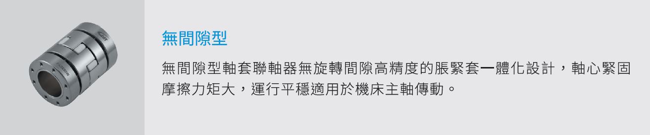
(1) There are five ways to fix the shaft.
(2) Fastening bolts or countersunk head bolts should be properly tightened using a hex wrench or torque wrench.
Coupling installation diagram
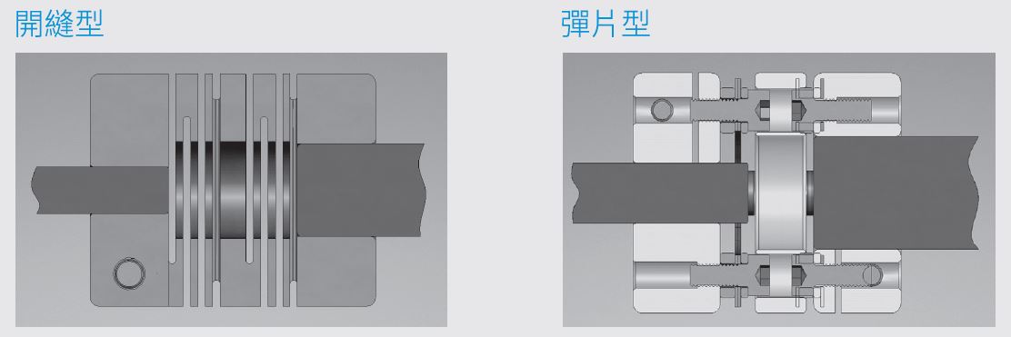
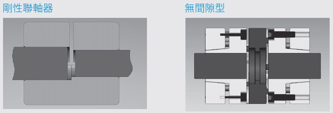
♦ To ensure proper installation of all types of couplings, prevent contact between the two shafts, and maintain normal operation, it is recommended to assemble them according to the following diagram.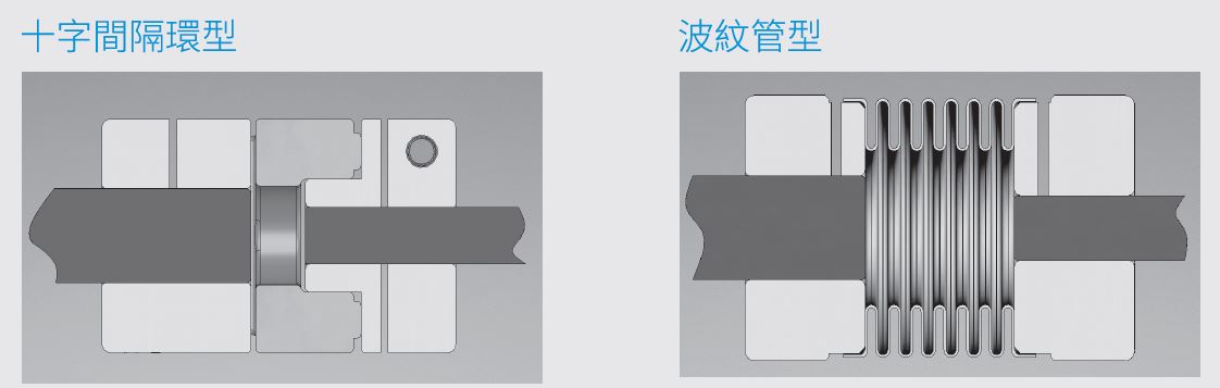
Coupling Selection Guide
♦ Induction motor
(1) It has more than 3 times the torque during instantaneous rotation.
(2) The motor spindle will have a reciprocating motion of ±1.5mm during operation. It is not recommended to use the slotted type.
(3) If a DC motor is used, it can be used in a dusty working environment.
♦ Stepper motor
(1) There is no 3 times the torque during instantaneous rotation, but it is the maximum rated torque of the motor.
(2) The torque at low speeds is greater than that of servo motors of the same class.
(3) The higher the motor speed, the lower the torque.
(4) The motor will heat up during continuous operation (this can be mitigated by using a spring-loaded type).
* Stepper motors have lower output power than servo motors.
♦ Servo motor
(1) It has more than 3 times the torque during instantaneous rotation.
(2) Within the rated speed range, the torque is the rated torque.
(3) The torque is the same at low speed and high speed.
(4) The motor temperature rise is very small during continuous operation.
♦ Encoder
(1) Built into the servo motor, with extremely low driving torque
(2) Or connected to a stepper motor (optional)

Model