Cookies help us deliver our services. By using our services, you agree to our use of cookies.
Search
-01_4.jpeg "GMTGLOBALINC")
English
- CAD Model Selection
- Support
- Events
- About GMT
- semiconductor and optical communications industries solutions
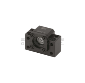
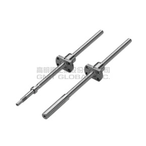
- Linear Motion Components
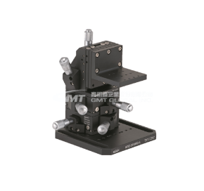
- Manual Stages
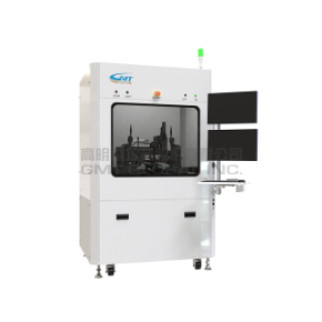
- Motorized Stages
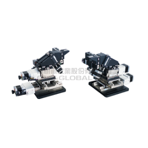
- Alignment Stages
- Direct Drive Module Series
- Automation Module Series
- Optical Components
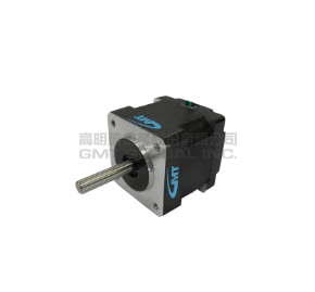
- Motor/Drive
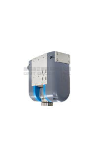
- Shrink Fit Machine
- Stamping & Mould Components
- INVESTOR AREA
- Contact Us
- NEWS
Payment options


